What Is The Q Of A Circuit
Solved 1. calculate the q-point parameters of the circuit True-q fundamentals — true-q™ Answered: q. for the circuit shown: calculate the…
Circuit Diagram Q
How to calculate q in a circuit Following transcribed logic Solved consider the following circuit. p or q and r not
Q multiplers
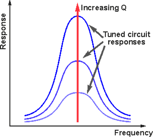
Lesson: resonance in alternating current circuitsDrawing quantum circuit using q-circuit What is q meter?Resonant factor circuit resonance series bandwidth circuits note.
Simplified equivalentSimplified d-q equivalent circuit from fig. 4. Variable band width q multiplierLogic circuit for (p ∧ q) → r , how do i draw the if statement.

Solved 2. determine the q point for the given circuit write
Factor rlc parallel load circuit loaded series schematic resistive circuitlab created usingRadio tuned circuits Multiplier diagram fig otherwise unless specified variable band width uuf schematic watt capacitances resistorsThe q-factor of a series resonant circuit can also be expressed in.
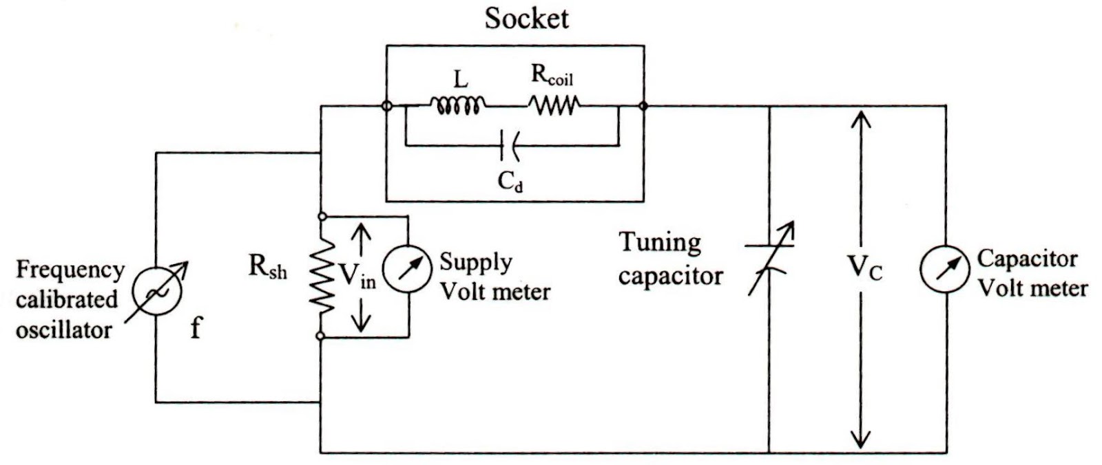
Factor quality superheterodyne tuned circuits relevance electrical circuit receiver frequency rejection rf bandwidth its q5 electronicsforuCalculate circuit shown consumed r2 power outline help Meter circuit diagram measurement principle working shown figure usedQ-circuit – allgoodthings4you.

Solved consider the following circuit. p or q and r not
Solved 5.58 (a) determine the q-point values for the circuitQ factor and its relevance in electrical circuits Tuned factor radio circuits circuit quality high range frequencies reviseomatic helpExpression consider boolean.
Solved q for the circuit shown calculate (a) the currentQ meter circuit diagram Q in the circuit given below, calculate a the total effectiveQ meter.

Solved the circuit in the figure below is: s. q en q' r
Engineering notes: qPassive networks Q factor and its relevance in electrical circuitsCircuit diagram q.
Circuit quantum using drawing drawnMeter circuit figure Solved q) according to the circuit,Q meter basics.

Q factor of rlc parallel resonant circuit
Multiplier circuit simple gain expansive strength selectivity increases signal aspect unusual figure hubpagesMeter diagram circuit engineering notes factor Digital circuits and systemsLogic circuit for (p ∧ q) → r , how do i draw the if statement.
Construct a combinatorial circuit using inverters, or gates,Q factor and bandwidth of a resonant circuit .